| |
The
eLPC 144 Module is a SOM (System On Module) based on
the NXP LPC 2294 microprocessor. This module was designed and is produced
by eSysTech as one of the alternatives in the eSysTech eLPC family of
modules.
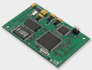 |
The
eLPC Module consists of a credit card size PCB
that implements the core of a microprocessor system based on the
ARM7TDMI-S architecture.
The
eLPC Module follows the baby-board concept, or
microprocessor module, in other words, implements the essential
functions (processor, Flash memory, RAM, power, and clock) of
a board and provides interfaces for the implementation of specific
functions for each product.
|
Characteristics
of the Module
The
products that utilize the eLPC144 Module are typically composites of
a mainboard on which is connected the eLPC144 (baby-board). In the mainboard
are implemented the specific circuits of each product. The two headers,
connectors in white in the photo, allow the connection between the main
board and the eLPC 144 Module.
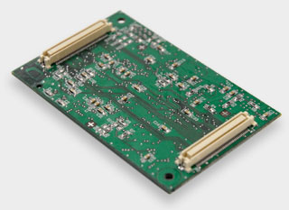
The
figure below shows the back face of the module that contains the two
high density connectors (total of 160 pins).
The main
characteristics of the eLPC 144 Module are listed in
the table below.
•
NXP LPC2294 Processor, containing:
- ARM7TDMI-S core
- programmable clock of up to
60 MHz
- bus controller for 8 chip
selects (2 availables)
- interrupts controller
- 58 I/O pins
- internal Flash of 256 KBytes
- internal RAM of 16 KBytes
- 6 timers of 32 bits
- 2 USARTs
- 2 SPI
- ADC
- 8 analog input channels of
10 bits
- 4 CAN ports
- 1 I2C port
- power management unit
- RTC |
| •
External SRAM of 1 MBytes (512 K x 16 bits), 55 ns (can be mounted
with other models) |
| •
External FLASH of 2 MBytes ( 1 M x 16 bits), 70 ns, Intel TE28F160B
(can be mounted with other models) |
| •
Input feed of 5V, max. 200 mA. On-board tension regulators generating
3.3V for the digital and analog circuits of the board. 3.3 V digital
outputs are available in the connector with external current capacity
of 200 mA. |
| •
Programmable Logic: one CPLD Xilinx XC9536XL with 36 logic cells
(can be mounted with a CPLD model of 72 logic cells). |
| •
Bus Connectors: 160 pins providing the signals and feed lines of
the module for the mainboard. |
| •
JTAG Connector of the Processor: interface utilized for depuration
of software and for recording of the Flash memory. |
| •
JTAG Connector of the CPLD: interface utilized for recording of
the CPLD using apparatus for recording of Xilinx. The CPLD can also
be recorded through the module connectors. |
|